MICROPHONES
North Suburban HAMMOND ORGAN Service
One of the more important considerations regarding microphones is impedance. This term refers to opposition to current flow. Impedance is similar in some ways to simple resistance, which is a physical property of substances and refers to how well or poorly they conduct electrical current. Impedance, however takes into consideration two additional properties known as inductive reactance and capacitive reactance. Reactance of either type for practical purposes of this discussion only concerns alternating current, and of course that is what an audio signal is, a complex alternating current representing the electrical analog of a soundwave in air. Essentially, we can say that impedance is opposition to alternating current flow in a device or circuit.
A small signal in a high impedance circuit is very susceptible to outside influences, such as ordinary power line hum and also radio and TV signal interference. Larger signals in low impedance circuits are affected very little by these influences. Losses in audio cables increase with cable length. So if you start out with a tiny signal and a high impedance circuit, you only need as little as a few inches of cable before hum, noise and serious signal loss take place.
Microphone outputs are generally small signals, with the exception of some carbon mics. Crystal mics can send out a high voltage signal, but crystal mics have high impedance, and condenser mics, even though they are generally the best, put out both a high impedance and a very low value signal.
The most efficient, or most loss-free transmission of signals takes place when the impedances of both the device that sends out the signal (microphone for the sake of this discussion) and which receives the signal (amplifier, recorder, etc.) are equal, or at least reasonably close.
There is lots of latitude within which things can work very well, but the impedance of both the microphone and the input to the amplifier or recorder should be in the same ballpark. Because low to moderate impedance signals can be transmitted over cables for much longer distances, we will find that most microphones include a means of optimizing their output signal impedance to a range that corresponds roughly to the devices that they are usually connected to. But if the microphone input on the far end of the mic cable is somewhat higher, this may actually be helpful. Interesting!
It's also important to consider what happens in modern, solid state amplifiers and speakers regarding impedance. In the early days of vacuum tube amplifiers with output transformers, impedance matching was more important, however in modern solid state amplifiers striving to match impedances can actually introduce some distortion. One other thing that we must also be aware of regarding impedance is that to have a really relevant discussion of impedance, we also need to consider what frequency we are looking at, because impedance changes with frequency. Much has been written aboute impedance matching; there is no need to repeat that here when a simple Google search will give you more information than you might ever want. What is important regarding microphones is that we should avoid really high impedance circuits carrying very low amplitude signals as these can introduce serious signal degradation in very short distances. Which is why there's a special preamp in a condenser microphone.
I once tried taking the output of a Wurlitzer electrostatic organ reed unit and running it through about 6 feet of shielded cable to the preamp input on a power amplifier. The resulting signal was terrible. I not only picked up some 60 Hz hum, but the upper end of the audio range was severely limited. However, when you plug the output of the reed unit into the preamp in the console, the resulting sound is infinitely better.
Regarding microphones, the easiest way to change impedance is with a simple transformer. The high impedance section has many turns of fine wire, and the low impedance side has fewer turns of heavier wire. Thus, the ribbon of a ribbon microphone which is very low impedance would connect to the winding with few turns of heavier wire, and the other winding with more turns of finer wire would send a slightly higher impedance signal off to the pre- or power amplifier. In condenser microphones, the capsule output is very small and very high impedance. In these, the on-board preamp in the microphone both amplifies the signal and outputs at a much lower impedance than that of the capsule. Although not a hard and fast rule, generally low impedance is below 600 Ω, medium impedance is 601 to 10,000 Ω, and over 10,001 Ω is high impedance.
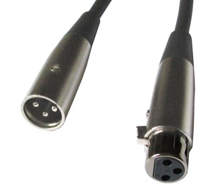
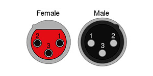
Better microphones also output a balanced signal, and they generally use XLR connectors. Here's what XLR plugs and sockets for microphones look like. There are three pins instead of the normal two. Pin 1 is the ground connection, pin 2 is considered the positive or "hot" signal, and pin 3 is the "cold" or negative side of the signal. The use of terms such as hot or cold or positive and negative are used as general conventions, and not intended to express actual polarity, which is constantly changing because the signal is AC.

Figure 20. male, (left) and female (right) XLR connectors, the standard used on all better microphones.
The signal on pin 2 is at a higher potential than that on pin 3, and the phase of the signals on the two lines (2 and 3) is 180° out of phase or completely opposite. The idea is that the audio signal is of different potential on lines two and three, and therefore there must be an output. However, hum, noise and radio frequency interference that get induced in the mic cable will affect both signal lines equally. Because they are 180° out of phase, the hum and noise signals are equal and opposite, therefore they cancel out. The result is a clean, noise and hum-free audio signal.
This article relates to the type of microphones that we would use for the recording of music, so we will not devote space to the typical tip-sleeve 1/4" or RCA unbalanced signal line connectors as the microphones which utilize these would not be suitable for serious musical work. Quality mics with XLR connections will work very well for speech as well as music, therefore the use of high quality microphones is beneficial in that application as well.

Figure 21. Pinout arrangement for microphone XLR connectors. 1 = ground, 2 = signal+ , and 3 = signal-.
We hope you have found this both interesting and helpful. High quality dynamic, ribbon or condenser microphones and XLR microphone cables and equipment are absolutely essential if you wish to make really good quality recordings of music and do it via microphones.
Page 10. Previous page