The HAMMOND ORGAN
North Suburban HAMMOND ORGAN Service
Jeesh! My Hammond organ is nuclear??" you might say when you see the word "reactor" used in the X66 article. Not so at all. A saturable reactor is really in a sense a special type of transformer. Saturable reactors are used to control the flow of alternating current in some circuits. Because audio signals are alternating current (AC) signals, we can use a saturable reactor to control audio AC.
The saturable reactor works by having a winding through which alternating current flows. On the iron core of this special transformer, there is a second coil or winding through which we send direct current, or DC. When DC flows through this coil, it magnetizes the iron core of the saturable reactor. Now, rather than go into a hugely detailed explanation of electromagnetic induction and the effects of inductance in a circuit through with AC flows, all of which you can find in google by searching these terms, I will confine this explanation to the way in which the Hammond engineers used saturable reactors to control certain audio AC signals in the lower end of the X66 drawbar section for the purpose of introducing vibrato.
Anyhow, an inductive device opposes the flow of alternating current. The opposition is called inductive reactance. This simply says that if we send an audio AC signal through a coil wrapped around an iron core (which constitutes an inductive device) the coil will oppose the flow of AC in the circuit. It won't eliminate it entirely, but it will oppose it to at least some degree, the amount depending on both the amount of inductance in the coil and also the frequency of the AC signal. All things being equal, the inductive reactive opposition to the flow of AC INCREASES as the frequency of the current increases. This we can easily prove by showing the formula for calculating inductive reactance in an inductive device which is this:
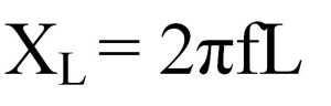
In the formula, XL is the inductive reactance in ohms; f is the frequency of the AC, and L is the physical inductance of the device in question. As you can see, Pi is in there too. But without getting into it any further here, if you know even the fundamentals of algebra, you'll see that XL must increase with an increase in frequency.
Now, suppose, however, that by means of a second coil on this device, we begin to magnetize the iron core around which we wrapped our coil which is carrying the audio signal. As the core becomes more and more magnetized, the inductive opposition begins to decrease. When the core is fully magnetized (saturated) the inductive opposition has essentially disappeared. So therefore, the simple variation of a DC magnetizing flow in the control coil of the saturable reactor will subsequently control the flow of AC in the main coil. In the X66, as in the Wurlitzer vibrato system, we have to "gate" or control audio AC signals which differ in phase so that the resultant signal will change phase smoothly from one to the other, which as we know from reading the Hammond and Wurlitzer articles in this series results in a pitch change of the composite signal.
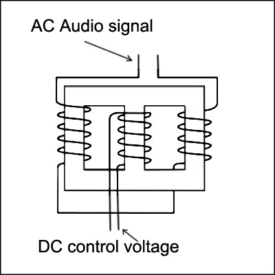
In real life, there are certain other considerations which govern the design of saturable reactors, and while the above describes the theory and the principle, an actual saturable reactor usually has three windings and two separate magnetic cores. The controlling DC winding wraps around part of each core, and there is a signal or AC winding on each of the two cores. The signal windings on the cores are wound so that current flows in the opposite direction through each of the signal windings. In simplified form, the saturable reactor in the X66 bass vibrato system uses a DC voltage which rises and falls at the vibrato rate to control the AC signals flowing through the signal coils on the saturable reactors and thus modulates between two AC signals which are out of phase with each other.
The 180° phase shift exists between audio signals on the emitters and collectors of transistors used in these kinds of amplification configurations. In this particular application, when the control coil has no DC in it, the reactor blocks most of the AC audio signal from the emitters of the three transistor amplifiers and the output consists of the collector signals. When the DC control signal is at its maximum, the saturable reactors lose their reactance (and subsequently their impedance) and the signals on the emitters have a much easier path and because of the impedance presented to the signals on the collectors by the 1 mic capacitors and the 15K resistors, most of the signal under this condition is that from the emitters of the transistors.A typical saturable reactor in schematic form looks like this: