Wurlitzer 4600 series
North Suburban Hammond Organ Service
In order to use the AC audio voltage that results when we zap one or more of the pickups on a reed with DC, we need to do two things. First, we have to put a resistor in series with the reed and the power supply. The AC that develops is actually a very small, low-amplitude signal. The resistance to DC represented by the reed and an associated pickup is exceedingly high because there is no connection between the two. In fact, the resistance is essentially infinite.

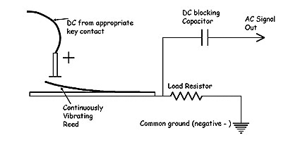
Figure 5. This schematic shows how both the load resistor and a DC blocking capacitor are integrated into the circuit.
In order to get the AC audio signal from the resulting AC that flows into and out of the reed capacitor as the reed vibrates, we have to put a resistor in series with the reed as you see here in figure five. Then as the AC flows into and out of the capacitor that is formed by the reed and a pickup, this alternating current flow will develop a voltage across the resistor. This resistor is called a "load" resistor.
The second thing that we must do is to put a regular capacitor in the signal output path from the load resistor. Capacitors block direct current. Once the charge is built up so that the voltage across the capacitor equals the charging DC voltage, no further DC flow is possible. However, alternating current flow is possible in any circuit containing capacitance. The reason for this is that as we just showed, AC can flow into and out of a capacitor. Now, to be literally correct, AC can't really flow through a capacitor.
Because the two plates of a capacitor are separated from each other, a capacitor is not a continuous, conductive circuit path. However, we're going to think like lawyers here and look for a loophole. Because AC can flow into and out of a capacitor, when a capacitor is part of a circuit, it BEHAVES as though AC can flow through it. Therefore, we can correctly speak of AC as flowing through a capacitor, because the capacitor indeed behaves, with respect to the rest of the circuit, as though it was allowing AC to flow through itself. Therefore, we put a capacitor in the signal output path from the load resistor, and it effectively allows the AC signal, but only the AC signal, to pass through and go on to subsequent parts of the circuit. It does not allow the DC which is also present to pass along. Therefore, we can state, and indeed the behavior of the circuit allows us to state accurately, that this regular capacitor at the output of the load resistor blocks the DC charging voltage which is across the reed and one or more of its pickups, but allows the AC audio waveform to continue on.
What is actually happening is that when the reed is vibrating and we zap one or more pickups with DC (from the key contacts) we have a circuit in which an AC waveform is riding on top of a steady DC voltage. The load resistor makes this AC wave-form accessible, and the extra capacitor allows us to take just the AC audio waveform and send it off to wherever we want it to go. In the Wurlitzer electrostatic organ, this and other AC audio waveforms from the reed pickups go on to further amplification and also, if the musician desires, through a special circuit which adds vibrato. Here, in very simple form, is what this circuit looks like. For simplicity, we show a reed with just one pickup. Notice that here we attach the load resistor to the reed and not to the electrode. The reason for this is on the next page.
Previous Page Page 5. Next page