X 66
North Suburban HAMMOND ORGAN Service
The synchronizer, as you saw on the previous page is really an amplifier that amplifies the small signals from the tone generator and also, by means of clipping, changes them to square waves. Part of the output of each synchronizer consists of signals for the highest octave of generated tones on the instrument. The rest of the output goes to the input of a so-called flip-flop frequency divider.
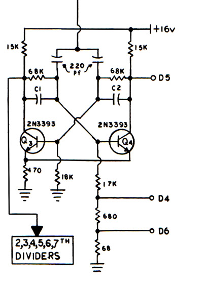
Figure 9.
If a given tone is exactly an octave higher than another tone, then it has exactly twice the frequency of the original tone. Likewise, lower octaves of the same note have frequencies exactly half of that of the previous higher note. Because of this 2:1 ratio of signals exactly an octave apart, it is possible to take a particular frequency and electronically divide it by two, so that for every two input cycles, there will be only one output cycle.
Flip-flops are circuits that can attain either one of two stable states. So for every two input cycles, the flip-flop cycles once through each of its two states. If we use the signal from just one side of a flip-flop, then that signal will have one cycle for every two input cycles, or exactly half of the frequency of the input. With the exception of the notes in the highest octave of the X66, which come directly from the synchronizer*, all of the lower tones come from a series of flip-flop frequency dividers that follow the synchronizers.
Thus, we can take one high frequency reference tone from a tone wheel generator, amplify it, clip† it into a square wave, and then get all of the lower octaves of that note, all the way down to the lowest pedal tones from a simple series of 2:1 frequency dividers. In this instance, a portion of the output of each frequency divider stage is used for the input of the next stage. Since these circuits are flip-flops, they output square waves if nothing else is done to modify them.
The signal from the synchronizer comes in from the wire leading down from the top of the picture, Figure nine, to the junction between the two 220 pF capacitors. A square wave signal forms on the collector of transistor Q3 and goes on to the next lower divider. A square wave also appears at terminal D5 where it goes to a particular so-called proportional keyer associated with the drawbar system for the harmonic synthesis system.
In a standard flip-flop of this type, both of the cross-coupling capacitors listed as C1 and C2 would be equal, but in this circuit they are not. The values are scaled according to the number of a particular divider stage, but C1 has a much higher value than C2. (nominally ten times greater). This makes the waveform that appears on the base of transistor Q4 somewhat of a sawtooth wave which has both odd and even harmonics. This modified sawtooth waveform is available at terminal D4 where it's used for those imitative voices where a formanted sawtooth would be the best method of imitating such instruments.
A smaller value of this sawtooth wave is also available at terminal D6 where it goes to the percussion system. As we see here, both square wave signals and sawtooth wave signals are output by the tone generator. It is interesting by way of comparison that in the electrostatic Wurlitzers, two or three different waveforms are also available from each tone source. In the Wurlitzer, however, the waveforms receive no further formanting or other filtering or shape-changing and are used as is from the tone generator.
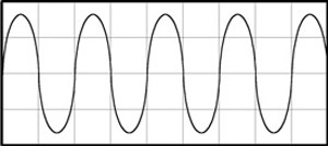
Figure 10.
In the Hammond X66, as we'll see on following pages, these primary waveforms undergo further filtering, the square waves being transformed to sine waves, and the sawtooth waves getting formanted for the so-called bright voices [Hammond's term]. Interestingly, the sawtooth waveforms available at terminal D4 which go to the percussion system also undergo both formanting for some voices, and filtering down to approximate sine waves for other voices.
The needs of both the additive harmonic synthesis system and the formant system are so different that it is better to make different waveforms in the tone generator than to try to make just one type of waveform do everything. Just as the traditional Hammonds did not do a very good job at imitating most reed and string tones, instruments which relied only on formanting did not do very well in imitating either flutes or various percussion sounds.
* On the X66, there is also a very top C. It is produced by taking the square wave signal from the next to the highest F and extracting the third harmonic of this F. The pitch of the third harmonic of F is very close to the pitch of C, and it was actually easier for the Hammond people to derive top C by tripling the second highest F rather than adding an extra tone wheel. This signal is a sine wave, which is fine, because with a fundamental frequency of approximately 8372 Hz. all harmonics above the second (16744) would be ultrasonic, and most adults have a hard time hearing sounds above 15Khz anyhow. No useful purpose would be served by providing any harmonics for this pitch.
When the large amplitude sine wave figure ten, goes through an amplification circuit in which the high amplitude peaks drive the amplifier into its non-linear or saturation range, the result is that the tops and bottoms of the sine wave get clipped which results in a very good approximation of a square wave figure eleven. A reasonably good square wave is required as the initial input triggering source for the X66 frequency dividers.
† If you amplify a sine wave to a value that is beyond the linear portion of an amplification stage, the result is clipping, that is, electrically flattening the tops and bottoms of the sine wave. As figure eleven shows, a clipped sine wave then takes on the appearance and characteristics of a square wave.
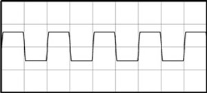
Figure 11.
Previous Page Page 8. Next page