MICROPHONES
North Suburban HAMMOND ORGAN Service
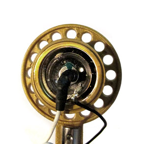
Here's a look at the opposite side of the microphone capsule. It is difficult to see all in too much detail, and generally the disassembly of a microphone beyond this point is extremely risky. Fortunately, very little usually goes wrong in here anyhow! Here we see the two wires leaving the capsule assembly. These wires carry the extremely low-level, high impedance signal. They are shielded against 60 Hz power hum and radio frequency interference by normally being enclosed in the metal of the microphone case, and in this particular microphone they extend a little over an inch and a half before they encounter the mic preamplifier.

Figure 12. A look at the rear side of a condenser microphone capsule, signal leads attached. Although hard to see in the picture, this is built a lot like a fine watch in terms of accuracy and precision.
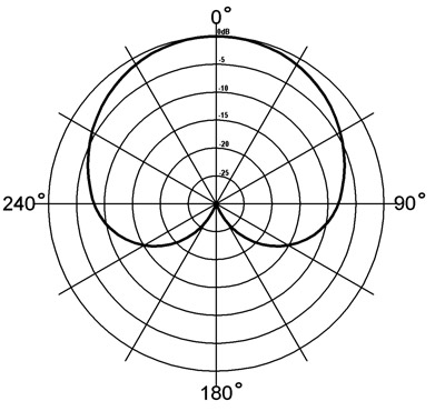
This particular microphone, as is true of many others, has a cardioid response pattern. The word cardioid refers to the approximate heart-shape of the response curve, and the picture below shows what this looks like.

Figure 13. Polar graph showing a cardioid response pattern, typical of many professional usage microphones. This is looking down at the microphone which would be at the center of the graph, and it shows that sounds that originate beside the microphone are somewhat reduced, and sounds coming from behind the microphone get substantially reduced. This makes the microphone favor sounds originating from the front and eliminates unwanted noises.
Around the outer circle of this graph are degree notations, and then down the upper center are the decibel or dB levels. The decibel ratings show the amount of signal reduction that occurs. The top of the graph, or the zero position has no reduction as indicated by the 0 dB designation. As we go progressively around the circle, we see that we begin to pick up more decibels' worth of signal reduction until we get to the 180° position which would be directly behind the microphone. Here, we get around a 25 dB reduction in response. Because of the logarithmic nature of a decibel scale (which corresponds roughly to the way people hear stuff) the actual reduction is very substantial.
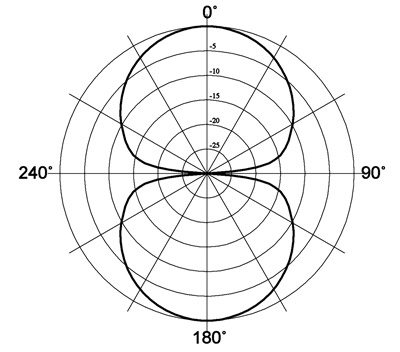
The cardioid pattern is not the only one, however, but it is generally the most useful for most applications. Another response pattern which is very useful in certain situations is the figure-eight pattern. See figure fourteen. If you were to record a church pipe organ for example, with pipe chambers on each side of the chancel (very common in many Episcopal churches in particular but not limited to that denomination) a figure-eight microphone could be very useful.
There is another microphone response pattern that is also useful on occasion, and that is the omni-directional pattern. As the name implies, omni-directional microphones pick up sound pretty much evenly regardless of where it is coming from. There's no need to show a diagram of the response pattern of an omni mic. It would just be a circle on the graph. If you are recording a musical event and you perhaps want to get a lot of the hall ambience as well, then an omni-direction microphone would be a good choice. The cheap microphones that used to come with early non-professional amateur-use tape recorders were omni-directional. There are also some commercial microphones that have all three response patterns and you can select the pattern you want by means of a switch on the microphone itself. We should also mention that most professional recordings of musical events make use of mutliple microphones and also multi-track recorders that can record more than two tracks simultaneously.
Most consumers do not have equipment to play these multiple-track recordings; they are generally limited to commercial music studios. The usual procedure is for a recording engineer to listen to the multitrack recording during the process called the mixdown, where the multiple audio tracks are combined into a standard two-track stereo recording for release on a CD or DVD or perhaps as a download from an on-line music site.

Figure 14. Polar graph showing a figure eight response pattern, typical of most ribbon microphones, and also available in condenser mics if desired. This is looking down at the microphone which would be at the center of the graph, and it shows that sounds that originate on either side the microphone are somewhat reduced, and sounds coming from in front of or behind the microphone get emphasized. This can be useful for picking up signals from two opposite sound sources.
When the recording engineer is satisfied with the result, then he makes a standard stereo recording of the completed mixdown, and this is what we get when we play our CDs, etc. During mixdown, the recording engineer has complete control over every single track of the multiple track recording. He can adjust the bass, the treble or the midrange independently. He can also decide where in the stereo field a particular track should be. He can also adjust the volume of each track. There are several other parameters which he can control at this stage, but the recording process for music, and electronic instruments in particular can be the subject of a different article for it is an interesting but very complex process.
Page 8. Previous page | Next page