The HAMMOND ORGAN
North Suburban HAMMOND ORGAN Service
How does a vacuum tube amplify a signal? Let’s begin by saying that a vacuum tube really does not amplify a signal in the true sense or definition of the word “amplify.” What the tube really does is to allow a very small or weak signal to control the flow of a much larger current so that any minute variations of the controlling signal current are reproduced accurately in the much larger current. Because the tiny variations of the input signal’s current are faithfully reproduced in the tube’s output current, which is much larger, in that sense the tube does amplify a small signal.
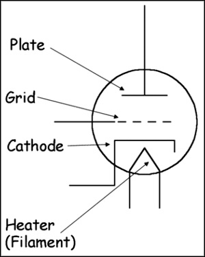
Figure 23. Schematic of a triode or three element tube which can serve as an amplifier. In operation, a heating filament receives (usually) six- or twelve volts AC. This AC heats the filament which, seen through the glass envelope of a typical tube will be glowing orange. The filament heats a metal structure called the cathode. At the other side of the tube is another metal structure known as the plate. When a DC voltage of the right polarity exists across the cathode and the plate, electrons leave the cathode and flow through the vacuum in the tube to the plate. This is called thermionic emission. The grid, placed between the cathode and the plate, receives the signal to be amplified. Very small changes in the grid voltage significantly modulate the current flow from the cathode to the plate, thus a minute signal voltage controls the flow of the much larger plate current. Within the operating limits of a particular tube, variations in grid voltage will be faithfully copied in the cathode to plate current, thus effectively "amplifying" the grid signal.
There are many variations in tube styles, and the above diagram only shows the tube itself. This diagram does not show any of the other associated components that we would find in a typical amplifying circuit. It is presented only to show the basic principle of a vacuum tube used as an amplifier. The signals which come from the Hammond tone generator are very small signals, being only a few millivolts in strength. There is no way possible that these signals could power any type of loudspeaker system. For this reason, you will find several different amplification stages in the Hammond console as stated on a previous page.
The final amplification in the console is an output stage, and here, the plate current of the output amplifying tube goes through the primary winding of another matching transformer. This transformer is much simpler than the matching transformer associated with the harmonic drawbars, and also it is wired in reverse, that is, the output from the final amplifying tube in the console goes through a high impedance primary winding with many turns of fine wire. The secondary winding of this transformer consists of a lot fewer turns of heavier wire and it has low impedance. It also has what is called a center tap which is grounded. Schematically it looks like figure twenty-four, below. The result is that the console output signal is what is referred to as a balanced or push-pull signal.
The reason for this is so that the console's output musical signal can be easily trans-mitted over considerable distances without picking up any interference or power line hum. This makes it possible to install a Hammond organ in a large hall or sports stadium. This low impedance, balanced signal can be transmitted hundreds of feet with no difficulty, thus a Hammond console in, for example, the press box of a ball park can send its musical signal to speakers all over the stadium, even to remote speakers that might be 500 or more feet away from the console.
As shown in this diagram, figure twenty-four, there are several other components associated with the vacuum tube consisting of resistors (zigzag line) and capacitors, shown by two parallel lines. Resistors limit the flow of current in a particular circuit. A voltage drop, dependent on the current flow exists across a resistor. They are used both to limit current flow and also to lower voltage by means of this current-related voltage drop.
Capacitors in these circuits are used for several purposes. One of the more important uses is to allow an alternating current to flow in the circuit, but to block direct current. Capacitors essentially consist of two metal plates which are close together but are separated by either air or some other insulating material. When direct current is applied to a capacitor, it causes a charge to exist on the plates, but once the plates are charged, no further current can flow in the circuit.
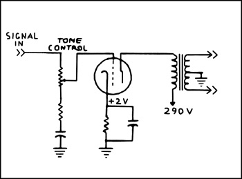
Figure 24. Simplified schematic of console output showing the impedance matching transformer in the plate circuit of the output amplifier tube. The signal is applied to the grid and causes the corresponding variation in the plate current which flows from the cathode to the plate, passing through the high impedance primary of the transformer. The signal enters (double arrows pointing in) A relatively high [290 volts] DC is applied to the plate as shown but it passes through the transformer primary. As plate current varies with the signal on the grid, the variations induce a current in the low impedance secondary of the transformer. The center or midpoint of the secondary winding is grounded as shown. The output signal develops across the entire secondary winding. The reason for the center tapped output winding on the matching transformer is so that any stray signals which might get induced into the output circuit will cancel out and be grounded, thus the output circuit will not pick up any extraneous 60 Hz hum from other sources. This makes it possible to run long output wires from the console as stated above on this page.
When an alternating current is applied to a capacitor, it alternately charges the plates, then discharges them and charges them to the opposite polarity, doing this continuously. Thus alternating current can flow in a circuit which has a capacitor. Effectively, we may state that an alternating current will flow through the capacitor, because the circuit behaves as though this were true. Because audio signals are always AC signals, they will effectively flow “through” a capacitor, but the DC voltages that exist on cathodes, grids and plates of tubes cannot get through or are blocked by the capacitors.
Capacitors also exhibit a property known as capacitive reactance. This is an opposition to the flow of AC in a circuit with a capacitor. If a capacitor is very small, it takes a very short time before the plates are charged. If it is bigger, it takes a longer time for the plates to charge. Therefore a bigger capacitor will allow a larger alternating current to flow in its associated circuit.
Note, however, that charging and discharging times are part of this situation. As the frequency of an alternating current increases, the time required between alternate chargings of the capacitor becomes smaller. A little thought on this will also show that therefore, more current can flow. Thus, the amount of reactance, or opposition to the flow of AC in a capacitive circuit is freqency-dependent, and this reactance will decrease as the frequency increases. Because the reactive effect of a capacitor is, therefore, frequency dependent, we can use a capacitor as a tone control.
In the output circuit in figure twenty-four, you see a label called “tone control.” There is a variable resistor [the zigzag with the arrow pointing to it]. If we lower this resistor’s value, a larger percentage of the signal is allowed to flow through a second resistor and then a capacitor to ground. Because the reactance of the capacitor decreases with increasing frequency, this means that the capacitor will let more of the treble frequencies partially short circuit to ground, thereby reducing the amount of treble which is allowed to get to the grid of the tube.
By sliding the arrow “up” the variable resistor, we let more of the signal go directly to the grid of the tube and likewise reduce the amount that gets shorted to ground through the capacitor. Thus the capacitor’s influence in the circuit is lowered, and therefore more treble gets through. There is one other capacitor here, known as a radio-frequency bypass capacitor. It has a very low value, and therefore very high reactance. If any radio frequency interference is present on the cathode, this capacitor shorts it to ground. But regarding the normal audio frequencies that exist in this circuit, this capacitor is too small to have any effect at all.
Previous page Page 13. Next page