The HAMMOND ORGAN
North Suburban HAMMOND ORGAN Service
The synchronous motor of the Hammond is very simple. In fact, it’s so simple that it has no means of starting by itself. Once brought up to speed, it can continue to run at 1200 RPM indefinitely and drive all of the tone wheels, but it can’t get off zero RPM without external help no matter how much AC you apply! A shaded pole induction motor is a simple motor which is self-starting. However, its speed is not constant enough to control the tuning of a musical instrument. But, by virtue of being self-starting, it can start a Hammond generator main shaft and accelerate it to and even slightly above its rated speed. Once the main shaft of the Hammond tone generator is running slightly over 1200 RPM, you can supply the synchronous motor with 60 Hz power, and it will immediately lock in step with the incoming AC, slow down, sync in and continue to run at 1200 RPM. The synchronous motor of the Hammond runs with a series of pulsations, one pulsation for each half cycle of the incoming 60 Hz. power. Just below is a flash animation that shows how the Hammond synchronous motor works.
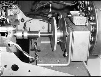
Figure 6. The somewhat elaborate coupling and mechanical vibration filtering between the synchronous motor and the input shaft of the Hammond tone generator. The roughly rectangular assembly to the right is the synchronous motor. Immediately following it are two flywheels with two springs at a forty-five degree angle between. Next you see a helical spring on the shaft just before the small mechanical coupling. All of these smooth out the output of the synchronous motor and deliver steady, vibration free rotation to the tone generator main shaft.
This means that it introduces a strong 120 Hz mechanical vibration into its output shaft. If coupled directly to the tone wheels, its 120 Hz vibration would carry over into the generated tones of the instrument and also make a loud 120 Hz mechanical buzzing noise. To prevent this, the synchronous motor is not rigidly coupled to the drive shaft, but rather drives it through a combination of three springs and two small flywheels. (See figure six.)
The springs absorb the pulsations and the flywheels further smooth out the rotation, just as the flywheels of engines smooth out the pulsations that result from the intermittent action of their cylinders. After this mechanical filtering, the precise 1200 RPM rotation of the main shaft is very smooth and contains no extraneous mechanical buzzing to make extra mechanical noise or introduce a spurious 120 Hz vibration into the tone wheel system.
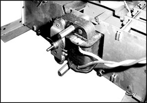
Figure 7. This is the shaded-pole induction motor at the back end of the Hammond tone generator. Its only purpose is to start the main shaft and accelerate it up to about 1450 RPM. Because the synchronous motor is coupled to the main shaft, it likewise gets pulled up to 1450 RPM. Then we can apply power to the synchronous motor which immediately slows to 1200 RPM, locks into step with the incoming power, and continues to turn the main shaft at exactly 1200 RPM as long as power is applied. As soon as the synchronous motor has pulled into sync and stabilized, the power to the shaded-pole starting motor is cut off, and a spring disengages the pinion on the start motor shaft.
As you study all of this, you really have to marvel at what a great piece of mechanical engineering the Hammond tone generator is. It is evident that a lot of thought went into its development and manufacture, a fact born out by how many of these Hammond instruments today are almost 80 years old and still function perfectly as well as the day they were made.
One of the interesting things about the Hammond synchronous motor, despite its simplicity, is that it is not self-starting. No matter how much AC voltage you put across it, it can't get off 0 RPM! Therefore, there is a second motor associated with the Hammond tone generator, located at the opposite end of the machine. This motor is a standard shaded-pole induction motor. Shaded pole motors are inherently self-starting, but their speed regulation is not close enough to control the accuracy of the Hammond tone generator tuning. Nevertheless, the shaded pole motor will start the system and bring it up to speed. The shaded pole motor in these Hammonds is a two-pole machine whose synchronous speed is 3600 RPM. On the end of this motor's shaft is a small pinion which meshes with a gear on the main tone generator shaft. The gear ratio is such that when driving the main shaft, the shaded pole motor gets it up to about 1450 RPM.
When you start a typical Hammond, you turn on a start switch that energizes the start motor. Normally the pinion on the start motor does not engage the gear on the main shaft, but when this motor is energized, its shaft moves endwise [via the motor's magnetic field] enough to engage the gear with the pinion. After the system is up to speed, you then turn on the run switch that applies power to the synchronous motor. Because the synchronous motor is now spinning (because it's coupled to the main shaft) it will sync in, immediately drop to 1200 RPM and continue to run. At the same time when the run motor is powered up, the run switch also places a resistor in series with the starting motor which reduces its torque so it slows down as the syncronous motor "grabs" the main shaft and locks it in to 1200 RPM exactly. Then you let go of the start switch. This cuts the power to the shaded pole starting motor, and as it's no-longer energized, a small spring pushes its pinion out of engagement with the gear on the main shaft. At this point the synchronous motor spins the main shaft entirely on its own and holds it exactly at 1200 RPM.
But wait! There’s more. The tone wheels are driven by gears from the main drive shaft, which itself is made up of a number of sections which are flexibly coupled together. The main shaft spins at 1200 RPM, but the tone wheels are geared from the main shaft at twelve different speeds.
Gear teeth typically introduce extraneous mechanical frequencies into any machinery in which gears are involved in power transmission. Therefore, the tone wheels are not rigidly coupled to their driving gears, but are arranged in pairs, two wheels to a single tone wheel shaft. Between each pair of tone wheels is a bakelite gear which drives the tone wheels through two helical springs. The bakelite gear can spin freely on the shaft; the pair of tone wheels being driven entirely through the springs. (Figure seven, next page.) The two tone wheels act also as flywheels, and the springs absorb the gear tooth ripple.
Figure 8, above. This is an elementary animation diagram of the Hammond synchronous motor. The rotor is a roughly six pointed star shaped piece of mild steel attached to the shaft. A laminated rectangular stator surrounds the rotor and has two pole projections which are wrapped with wire coils. Standard 120 volt, 60 cycle alternating current power is applied to both coils making the pole projections become magnets. The red arrows on the ends of the wires which lead into each coil denote which direction the AC is flowing at any moment.
The Hammond tone generating unit is divided into a series of compartments, with four tone wheels (in most cases) in each compartment. All four wheels in any compartment run at the same speed, but have different numbers of teeth. Thus they all generate the same note, but each produces a different octave of that note. As is true in any system where alternating currents flow through coils, there is some transformer action whereby the AC in one coil induces a small AC of the same frequency into adjacent coils. The Hammond tone generating system is no exception. One of the ways to eliminate this problem in the Hammond is to keep wheels and coils of unrelated frequencies magnetically shielded from each other. This is the main reason why the tone generating unit is divided into compartments separated by steel plates. Steel plate provides excellent magnetic shielding.
Previous page Page 4. Next page