The HAMMOND ORGAN
North Suburban HAMMOND ORGAN Service
One of the interesting sections of the Hammond amplification system is the percussion keying circuit, which is a variable gain amplifier that starts off at a high gain, and then the gain is gradually decreased as you hold a key down. This makes any signals passing through the percussion amplifier fade or "ring" off like the sound of a bell. The musician can select whether the percussion will be applied to either the second or third harmonic, and he can also control whether the tone will fade out very quickly, or fade more slowly.
As I mentioned on the previous page, the percussion effect is controlled by one single percussion keying circuit which means that the keyboard has to be treated as a unit, rather than having the percussion work on each key individually as it would in a real keyboard percussion instrument such as a celesta or a piano.
This of course is a drawback or a defect, as it does not parallel the way a real (non-electronic) musical instrument works. However, it has the advantage, (if you consider it such) in that the musician can bring the percussion effect in or out of his playing at will simply by changing from a very sustained, legato touch to a more detached or staccato touch. Whether this is truly an advantage in the real sense, or just a claimed advantage is open to individual interpretation.
However one looks at it, having a single percussion keying or "gating" circuit for the entire keyboard definitely makes the instrument simpler. By its very nature, a Hammond organ is a complicated machine. Laurens Hammond and his people were in business to sell instruments, and he had to tread a delicate path between making a good instrument and mak-ing a practical and not overly expensive instrument. In many playing situations, it makes no difference whether there is a single percussion keyer affecting an entire keyboard or individual keyers for each key.
The one area where Hammond absolutely did not compromise at all was on quality. Everything in a traditional Hammond is built extremely well, engineered to last, and the workmanship is exquisite. Even if you have no interest at all in music or instrument design, you will be impressed by the Swiss watch precision coupled with rugged construction that you always find when you look inside a traditional Hammond tone wheel organ.
Here (Figure twenty-five) is a schematic diagram of a typical Hammond organ percussion keyer. The basic theory of operation for Hammond Percussion is to take either the second or third harmonic from the appropriate drawbar from the upper manual, amplify it, return part of it to the same drawbar and send the balance through a control tube which, when triggered by pushing a key on the top manual, makes the tone fade away at a rate determined by the design of the circuit and to some degree adjustable by the musician.
When the percussion is in use, the signal goes to the input of the percussion amplifier shown as terminal H on transformer T4 and then gets amplified by the vacuum tube listed as V5. Note that the plate current of tube V5 goes through a winding on transformer T5. (We're using the same parts numbering here as Hammond used in their original schematics). The output winding provides a balanced or "push-pull" signal output. Note the similarity of this to the output circuit on the previous page. Note also that there's a small extra winding on T5, This is the signal that gets returned to the drawbar from which it was originally borrowed.
The balanced output from T5 goes to the grids of the two-section control tube listed as V7a and V7b. When you push a key, the signal to have percussion gets amplified by V7 and goes through transformer T6 to the percussion amplifier output as shown. At the same time, the capacitor which is listed as C31 starts to discharge which makes the signal fade away. It works as follows: Pushing a key connects terminal K to ground via the eighth harmonic busbar which is used for percussion triggering when the percussion is in use. This essentially grounds the plate of tube V6, stops conduction and isolates the cathode and control tube grid circuits. The grids in V7 then drop from about +25 volts to +15 volts in the time it takes for C31 to discharge through resistors R57 and R58. When this is completed, the percussion signal is cut off.
There can be no more percussion at all until all keys that may be held on the top keyboard are released which then lets the control tube grids return to +25 volts again. The time of this voltage rise is set by the time it takes for C31 to charge back up to +25 volts through resistors R55 and R56. Note that when all keys are released, terminal K is no longer grounded and then V6 conducts again, which lets the +33 volts get back onto the grids of V7. The voltage drops across R56 and R55 as well as the transformer winding and R52 and R54 are the reason why the grid voltage on the grids of V7 only gets to +25 volts instead of 33 volts.
As you can see, if Hammond had made independent percussion for each key of the top keyboard, he would have had to duplicate this circuit 61 times! So from a practical standpoint, using a single percussion gate or trigger for the entire keyboard made a lot of sense. Remember again that this circuit was developed before transistors were available. Much of what transistor circuits do could be accomplished with vacuum tube circuits also, just not as simply, efficiently or nicely! [And it would take up a lot more room in the instrument's console as well.]
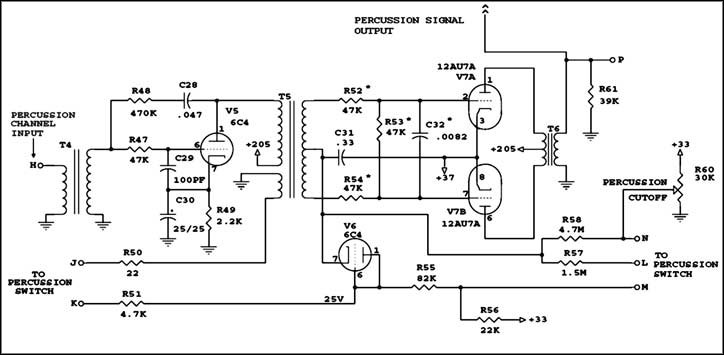
Hammond percussion circuit.
Previous page Page 14. Next page