The HAMMOND ORGAN
North Suburban HAMMOND ORGAN Service
On the previous page, you saw a schematic of the input stage of a Hammond power amplifier. This next illustration on this page shows the output section. There are four 6V6 pentode tubes arranged in such a way that the two pairs of parallel tubes handle the balanced signal. Each pair of tubes handles half of the signal. When set up this way, the result is a good, powerful and relatively distortion free signal. Tubes have a definite performance curve as do many other devices from springs to electromagnets. As long as you operate within the linear portion of the performance curve, distortion is minimal and the output faithfully imitates the input.
Figure 32. The output stage of a typical Hammond power amplifier showing the four 6V6 power pentode tubes, two tubes in parallel and the two parallel pairs in a push-pull configuration. High voltage DC plate voltage is applied through the center-tap on the primary winding of transformer T2 which as you will see has two secondary windings. The output of one goes to the speaker voice coils. The other secondary, which is center-tapped sends a negative feedback signal to the cathodes of the tubes. This helps to reduce distortion, inasmuch as any distortion in the output is applied 180 degrees out of phase to the input where it cancels distortion created in the amplifier stage.
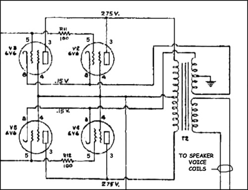
By using tubes in this "push-pull" configuration, the total output of the amplifier stage can be considerably greater because essentially only the positive halves of the electrical signal are handled by one pair of tubes, and the negative halves are handled by the other pair of tubes. Considering the tubes in this way, we can look at the entire amplification stage as a unit which has a much larger linear performance curve than a single tube by itself. As long as we operate within the linear portion of the performance curve, we may expect essentially distortion free amplification. As is the case with the illustration on the previous page, if you roll your cursor over the image, descriptions of essential parts will appear in small text boxes.
The next pages, which will be added soon, detail a typical solid-state [transistorized] power amplifier. Much of its operation will appear basically similar to what you see here; only the implementation is different.
Previous page Page 20.